Difference between revisions of "SETTINGS/General/Support Material/Support Options/Air Gap"
| (5 intermediate revisions by 2 users not shown) | |||
| Line 1: | Line 1: | ||
| + | {{Migrated|slice-settings/support/advanced#air-gap}} | ||
{{Slice Settings | {{Slice Settings | ||
| − | |The distance to skip between the support (including [[Settings/General/Support Material/Support Options/Interface Layers|interface layers]]) and the model. For | + | |The distance to skip between the support (including [[Settings/General/Support Material/Support Options/Interface Layers|interface layers]]) and the model. For ABS and PLA a value between 0.4 and 0.6 generally works well. |
In [[Release_Notes#1.5|MatterControl 1.5]], {{oldid|Settings/General/Support_Material/Support_Options/Air_Gap|1895|Z Gap}} was changed to Air Gap. Z Gap only worked in increments of the layer height. Air Gap can be any distance.|*millimeters (mm) | In [[Release_Notes#1.5|MatterControl 1.5]], {{oldid|Settings/General/Support_Material/Support_Options/Air_Gap|1895|Z Gap}} was changed to Air Gap. Z Gap only worked in increments of the layer height. Air Gap can be any distance.|*millimeters (mm) | ||
| Line 13: | Line 14: | ||
In this example, the distance between the top of the support material and the bottom of the model is 0.2 mm.}} | In this example, the distance between the top of the support material and the bottom of the model is 0.2 mm.}} | ||
| − | === | + | === Further details === |
| − | + | ==== Animation ==== | |
| − | [[File:Air Gap-ss- | + | Here's an animation which will hopefully demonstrate a little better how the air gap works. As you can see, the first layer of the part is lifted up for the air gap, but then for the second layer it moves back down to where it would have been otherwise. In other words, the air gap does not shift the entire object up, only the first layer. This ensures that the first layer is loosely connected to the support, but subsequent layers are printed normally. |
| + | |||
| + | [[File:Air Gap Animation.gif]] | ||
| + | |||
| + | ==== Exaggerated for clarity ==== | ||
| + | |||
| + | In this example we have set the air gap to 1mm (much larger than it should be) to illustrate how air gap works. | ||
| + | |||
| + | [[File:Air Gap-ss-ex2.png]] | ||
| + | |||
| + | The layer lines that are sitting on support material are printed with an offset of the air gap height (1mm). The parts that are not connected or touching the support material are printed at their normal layer height. | ||
| + | |||
| + | [[File:Air Gap-ss-ex3.png]] | ||
| + | |||
| + | The next layer (the one on top of support) is printed at its normal position, with no consideration of air gap at all. In this case (with the air gap sent to a very high value) actually below the air gapped sections. This is to ensure that support considerations do not actually change the geometry of the printed part. They are designed to only effect (attempt to affect) the adhesion of the material printed on top of support. | ||
| + | |||
| + | We recommend an air gap somewhere between .25 - .35 for a .35 - .5 nozzle. | ||
| + | |||
| + | [[File:Air Gap-ss-ex4.png]] | ||
Latest revision as of 11:51, 31 December 2018
|
|
Migrating: For MatterControl 2.0 the MatterControl documentation is moving to matterhackers.com/mattercontrol/support/. |
Function
The distance to skip between the support (including interface layers) and the model. For ABS and PLA a value between 0.4 and 0.6 generally works well.
In MatterControl 1.5, Z Gap was changed to Air Gap. Z Gap only worked in increments of the layer height. Air Gap can be any distance.
Parameters
- millimeters (mm)
Can be zero.
Example(s)
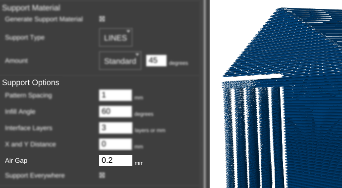
For this example, Support_test.stl is the model used.
mm
In this example, the distance between the top of the support material and the bottom of the model is 0.2 mm.
Further details
Animation
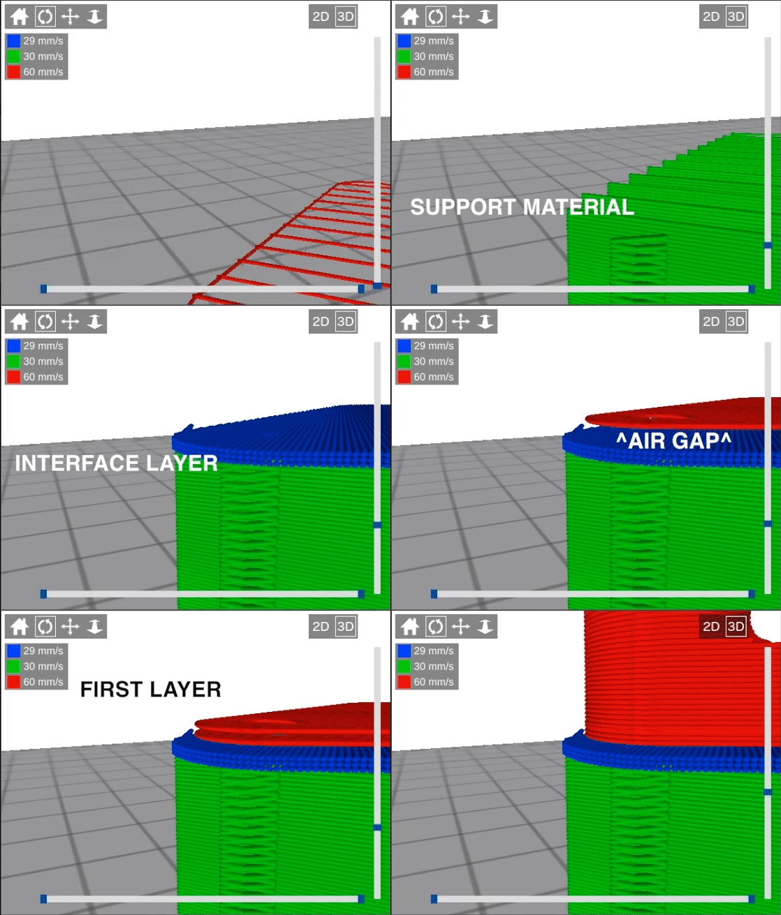
Here's an animation which will hopefully demonstrate a little better how the air gap works. As you can see, the first layer of the part is lifted up for the air gap, but then for the second layer it moves back down to where it would have been otherwise. In other words, the air gap does not shift the entire object up, only the first layer. This ensures that the first layer is loosely connected to the support, but subsequent layers are printed normally.
Exaggerated for clarity
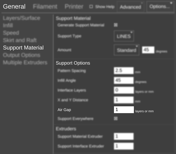
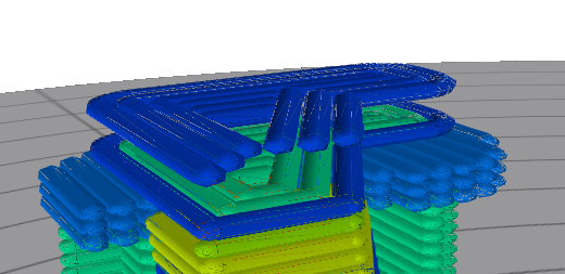
In this example we have set the air gap to 1mm (much larger than it should be) to illustrate how air gap works.
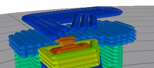
The layer lines that are sitting on support material are printed with an offset of the air gap height (1mm). The parts that are not connected or touching the support material are printed at their normal layer height.
The next layer (the one on top of support) is printed at its normal position, with no consideration of air gap at all. In this case (with the air gap sent to a very high value) actually below the air gapped sections. This is to ensure that support considerations do not actually change the geometry of the printed part. They are designed to only effect (attempt to affect) the adhesion of the material printed on top of support.
We recommend an air gap somewhere between .25 - .35 for a .35 - .5 nozzle.

