Difference between revisions of "LAYER VIEW"
(→Estimated Cost) |
|||
| (8 intermediate revisions by 2 users not shown) | |||
| Line 1: | Line 1: | ||
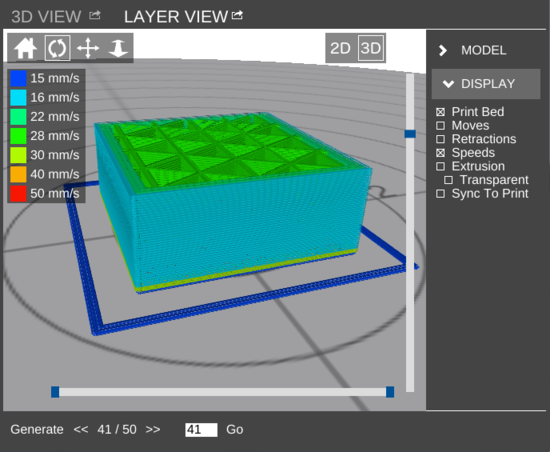
| − | [[ | + | __NOTOC__[[File:LAYER VIEW-ss.png|right|thumb|550px|<center>'''LAYER VIEW''' in 3D mode. Colors indicate speeds.</center>]] '''LAYER VIEW''' is a pane which allows the user to preview a print's G-Code tool path as a visual representation. It has two modes: 2D and 3D. ''Note'': 3D mode is not available on the [[MatterControl Touch]]. |
| − | + | ||
| − | [[File: | + | It is accessed by clicking the [[File:LAYER VIEW.png]] icon in the pane on the right side of the [[Main Screen]]. |
| − | = | + | The pane can be [[Pop out|popped out]] into its own window. [[File:Pop out.png|link=Pop out]] |
| − | + | == [[View Controls]] == | |
| − | [[ | + | |
| − | + | [[File:3D View-Controls.png]] | |
| − | [[File: | + | |
| − | + | View Controls is a set of tools which allow the user to manipulate the view and/or models currently displayed. | |
| − | [[File: | + | |
| − | [[Category: | + | In LAYER VIEW, the following tools are available: |
| + | |||
| + | *[[View Controls#Reset View|Reset View]] | ||
| + | *[[View Controls#Rotate|Rotate]] (only in [[#3D|3D mode]]) | ||
| + | *[[View Controls#Move|Move]] | ||
| + | *[[View Controls#Zoom|Zoom]] | ||
| + | |||
| + | == Mode Controls == | ||
| + | |||
| + | [[File:2D 3D.png]] | ||
| + | |||
| + | === 2D === | ||
| + | |||
| + | Enters LAYER VIEW's [[#2D mode|2D mode]]. | ||
| + | |||
| + | === 3D === | ||
| + | |||
| + | Enters LAYER VIEW's [[#3D mode|3D mode]]. | ||
| + | |||
| + | == Generate == | ||
| + | |||
| + | [[File:Generate.png]] | ||
| + | |||
| + | Slices the current model using the [[Settings|slice settings]] and displays the tool path. | ||
| + | |||
| + | == Graphical display == | ||
| + | |||
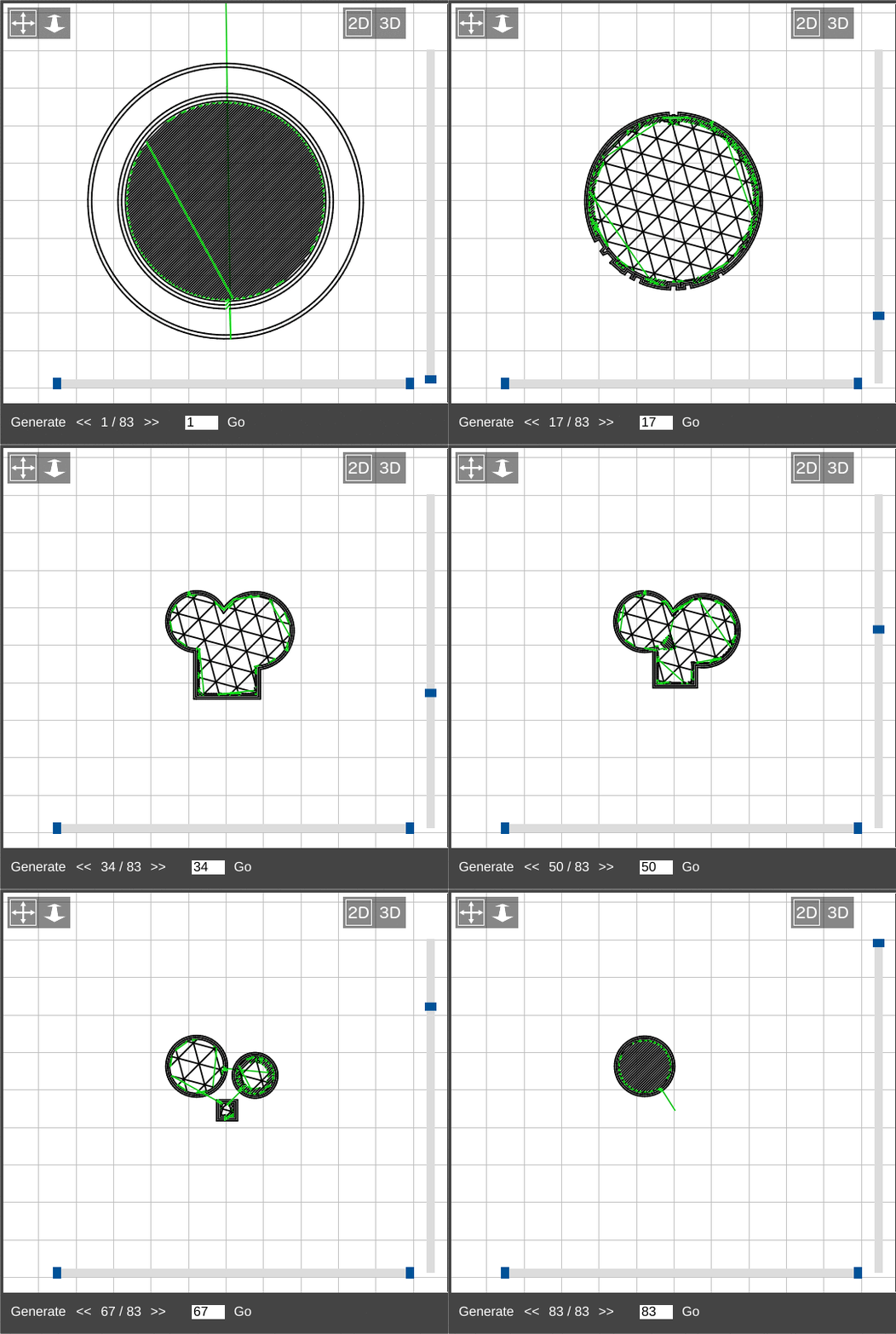
| + | [[File:Layers.gif|right|framed|<center>LAYER VIEW in 2D mode, showing each layer of the [[:File:MHObject.stl|MatterHackers test object]]</center>]] | ||
| + | |||
| + | Once G-Code for a model has been generated or loaded, the main area of the LAYER VIEW pane will display the tool path. Depending on which graphical display mode is selected, the toolpath is able to be displayed in different ways. | ||
| + | |||
| + | === Navigation === | ||
| + | |||
| + | [[File:Layer_View-Nav.png|none|framed|<center>Navigation for a 50-layer print. Layer 37 is currently displayed.</center>]] | ||
| + | |||
| + | ==== << ==== | ||
| + | |||
| + | Navigate down one layer. | ||
| + | |||
| + | ==== >> ==== | ||
| + | |||
| + | Navigate up one layer. | ||
| + | |||
| + | ==== # / # ==== | ||
| + | |||
| + | The currently displayed layer / total number of layers | ||
| + | |||
| + | ==== Go ==== | ||
| + | |||
| + | Navigate to the layer specified in the field to the left of the '''Go''' button. | ||
| + | |||
| + | === 2D mode === | ||
| + | |||
| + | '''2D mode''' displays one layer at a time in a two-dimensional graphic. | ||
| + | |||
| + | === 3D mode === | ||
| + | |||
| + | '''3D mode''' displays the tool path in a three-dimensional environment. The specified layer and any lower layers are shown. | ||
| + | |||
| + | == Sidebar == | ||
| + | |||
| + | The sidebar in LAYER VIEW has two sections: MODEL and DISPLAY. | ||
| + | |||
| + | [[File:LAYER VIEW-Sidebar.png]] | ||
| + | |||
| + | === MODEL === | ||
| + | |||
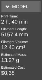
| + | Contains information about the print. | ||
| + | |||
| + | [[File:LAYER VIEW-MODEL.png]] | ||
| + | |||
| + | ==== Print Time ==== | ||
| + | |||
| + | The length of time the print is estimated to take. | ||
| + | |||
| + | ==== Filament Length ==== | ||
| + | |||
| + | The length of filament the print is estimated to use, in millimeters. | ||
| + | |||
| + | ==== Filament Volume ==== | ||
| + | |||
| + | The volume of filament the finished print is estimated to be, in cubic centimeters. | ||
| + | |||
| + | ==== Estimated Mass ==== | ||
| + | |||
| + | The estimated mass of the finished print, in grams. This is calculated as the [[SETTINGS/Filament/Material/Properties/Density|filament density]] in grams per cubic centimeter times [[LAYER_VIEW#Filament_Length|length of filament]], in centimeters, extruded. | ||
| + | |||
| + | ==== Estimated Cost ==== | ||
| + | |||
| + | The estimated cost of the print, based on the amount of material used, the [[SETTINGS/Filament/Material/Properties/Density|density]], and the [[SETTINGS/Filament/Material/Properties/Cost|price of the material]]. This information will not be visible if the material cost is set to 0. | ||
| + | |||
| + | === DISPLAY === | ||
| + | |||
| + | [[File:Layer_View-DISPLAY.png]] | ||
| + | |||
| + | ==== Print Bed ==== | ||
| + | |||
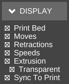
| + | Toggles the graphical display of the print bed. | ||
| + | |||
| + | ==== Moves ==== | ||
| + | |||
| + | Toggles the display of non-print moves in the tool path. | ||
| + | |||
| + | ==== Retractions ==== | ||
| + | |||
| + | Toggles the display of locations of the start and end of retraction events. | ||
| + | |||
| + | ==== Speeds ==== | ||
| + | |||
| + | Toggles the display of color-coding of the tool path to indicate the speed at which it is run. The tool path changes to a different color for each speed specified under the [[Settings/General/Speed|Speed sub-category]] in General settings. A legend is generated at the top left of the pane. | ||
| + | |||
| + | ==== Extrusion ==== | ||
| + | |||
| + | Toggles the display of visual representation of the flow as defined by the | ||
| + | |||
| + | ==== Transparent ==== | ||
| + | |||
| + | Toggles transparency of the tool path. Only available in [[#2D mode|2D mode]]. | ||
| + | |||
| + | ==== Sync To Print ==== | ||
| + | |||
| + | Draws the tool path in real time while a print is active. | ||
| + | |||
| + | [[Category:Features]] | ||
Latest revision as of 09:30, 1 November 2017
LAYER VIEW is a pane which allows the user to preview a print's G-Code tool path as a visual representation. It has two modes: 2D and 3D. Note: 3D mode is not available on the MatterControl Touch.It is accessed by clicking the ![]() icon in the pane on the right side of the Main Screen.
icon in the pane on the right side of the Main Screen.
The pane can be popped out into its own window. ![]()
View Controls
View Controls is a set of tools which allow the user to manipulate the view and/or models currently displayed.
In LAYER VIEW, the following tools are available:
- Reset View
- Rotate (only in 3D mode)
- Move
- Zoom
Mode Controls
2D
Enters LAYER VIEW's 2D mode.
3D
Enters LAYER VIEW's 3D mode.
Generate
Slices the current model using the slice settings and displays the tool path.
Graphical display

Once G-Code for a model has been generated or loaded, the main area of the LAYER VIEW pane will display the tool path. Depending on which graphical display mode is selected, the toolpath is able to be displayed in different ways.
<<
Navigate down one layer.
>>
Navigate up one layer.
# / #
The currently displayed layer / total number of layers
Go
Navigate to the layer specified in the field to the left of the Go button.
2D mode
2D mode displays one layer at a time in a two-dimensional graphic.
3D mode
3D mode displays the tool path in a three-dimensional environment. The specified layer and any lower layers are shown.
Sidebar
The sidebar in LAYER VIEW has two sections: MODEL and DISPLAY.
MODEL
Contains information about the print.
Print Time
The length of time the print is estimated to take.
Filament Length
The length of filament the print is estimated to use, in millimeters.
Filament Volume
The volume of filament the finished print is estimated to be, in cubic centimeters.
Estimated Mass
The estimated mass of the finished print, in grams. This is calculated as the filament density in grams per cubic centimeter times length of filament, in centimeters, extruded.
Estimated Cost
The estimated cost of the print, based on the amount of material used, the density, and the price of the material. This information will not be visible if the material cost is set to 0.
DISPLAY
Print Bed
Toggles the graphical display of the print bed.
Moves
Toggles the display of non-print moves in the tool path.
Retractions
Toggles the display of locations of the start and end of retraction events.
Speeds
Toggles the display of color-coding of the tool path to indicate the speed at which it is run. The tool path changes to a different color for each speed specified under the Speed sub-category in General settings. A legend is generated at the top left of the pane.
Extrusion
Toggles the display of visual representation of the flow as defined by the
Transparent
Toggles transparency of the tool path. Only available in 2D mode.
Sync To Print
Draws the tool path in real time while a print is active.


