Edit
< 3D VIEW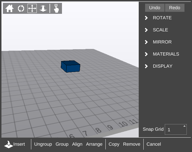
View Controls
Edit mode View Controls function much the same way as in the rest of 3D View, with the exception of the addition of the Select Part tool.
Select Part
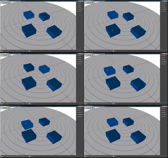
The Select Part tool allows the user to perform two functions:
- select a part by clicking on it
- move a part around on the X and Y axes on the bed by clicking and holding while moving the mouse.
Once selected, the part will display slightly brighter and a 3D black arrow icon (![]() will appear above.
will appear above.
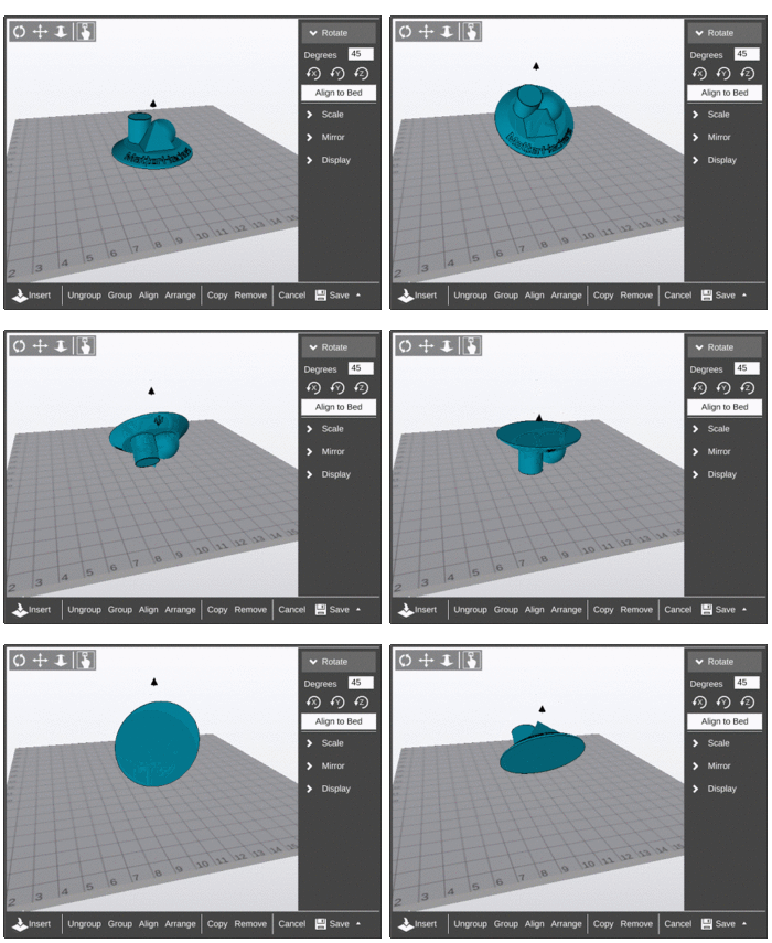
ROTATE
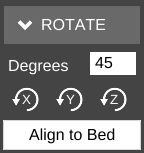
Degrees
Enter the number of degrees to rotate the model.
Axes buttons
Click the button for the axis around which to rotate the model to perform the rotation.
Align to Bed
Will cause MatterControl to attempt to bring the part down flat, adjacent to the bed. Useful for resetting the position of the model.
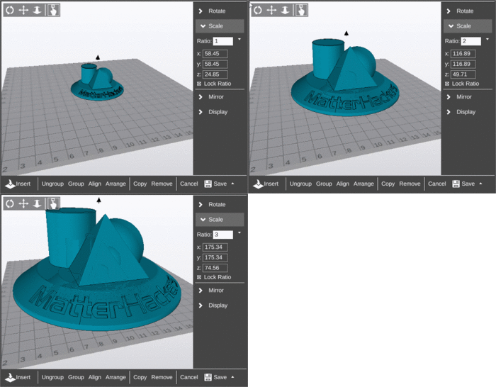
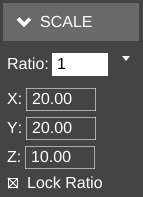
SCALE
Ratio
The Ratio field allows the user to specify a positive whole or decimal number which will be multiplied by the existing model's dimensions.
Presets
The Ratio field has several presets for common translations:
- mm to in (.0393)
- in to mm (25.4)
- mm to cm (.1)
- cm to mm (10)
- reset (1)
X
The X field allows for direct specification of the dimension of the model's size along the X axis.
Y
The Y field allows for direct specification of the dimension of the model's size along the Y axis.
Z
The Z field allows for direct specification of the dimension of the model's size along the Z axis.
Lock Ratio
If checked, the Lock Ratio option maintains the ratio of the model's dimensions relative to each other. For example, if a model's dimensions are X:20, Y:20, Z:50 and the Y value is changed to 10, X becomes 10 and Z becomes 25 automatically.
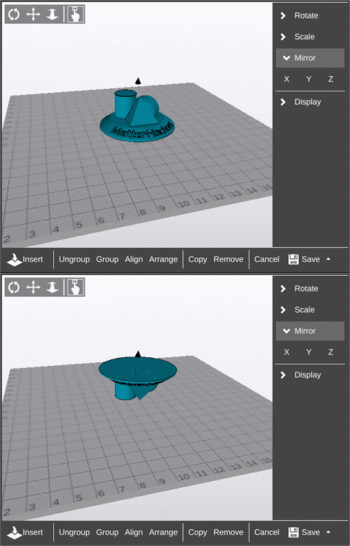
MIRROR
X
Click the X button to translate the model over the X axis.
Y
Click the 'Y button to translate the model over the Y axis.
Z
Click the Z button to translate the model over the Z axis.
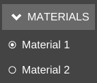
MATERIALS
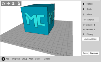
This section is shown only when the Extruder Count setting is set to a value greater than 1.
See also: Multi-Extrusion
DISPLAY
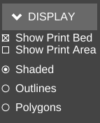
The DISPLAY section allows the user to toggle certain visual options.
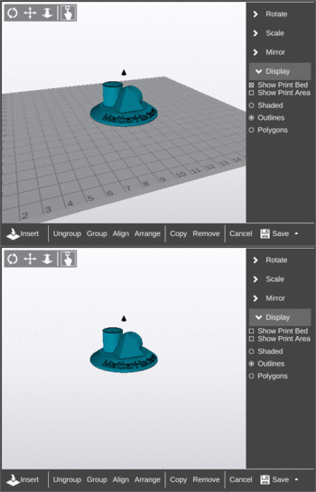
Show Print Bed
If enabled, the graphical print bed is displayed.
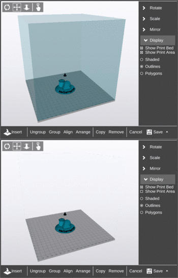
Show Print Area
If enabled, a translucent box appears to indicate the build volume. The box's height is set by the Build Height setting.
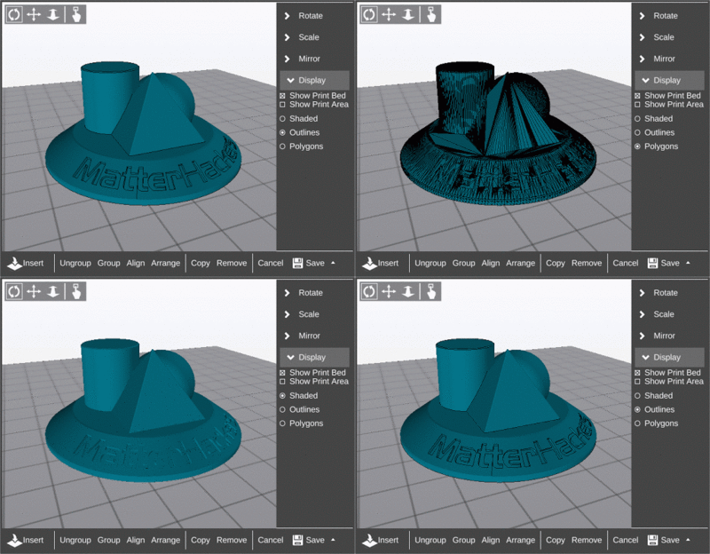
Shaded
Shows only the faces of the model.
Outlines
Shows the faces and lines of a model, but does not include lines which connect vertices of single flat polygons.
Polygons
Shows all faces and lines of a model, including all lines which connect vertices of single flat polygons.
Insert
Opens the operating system file manager so a model file can be selected for addition to any existing models in the current view.
Ungroup
Separates unconnected models. This is typically used if multiple models are loaded into MatterControl as part of one STL file.
Once ungrouped, the models can be selected and edited individually.
Group
Combines all models currently displayed. The combined "model" can then be selected and edited as a whole.
Align
Moves ungrouped models into a grid pattern relative to the currently selected model, then group all models.
